Explicit Solution Method
Explicit solution scheme simulates non-linear behavior without excessive memory requirements or the need for an iterative procedure. An efficient contact detection scheme and the explicit solution method used in PFC ensure that a wide variety of simulations are modeled accurately and efficiently, from rapid granular flow to brittle fracture of a stiff solid. The explicit solution scheme also provides stable solutions to unstable processes (e.g., collapse) and can describe non-linear behavior and localization with accuracy that cannot be matched by typical finite element programs. A quasi-static operating mode is also available for rapid convergence to a steady-state solution.
Automatic Timestep
Automatic timestep calculation ensures stable solutions and the explicit solution scheme simulates non-linear behavior without excessive memory requirements or the need for an iterative procedure.
Automatic multithreading
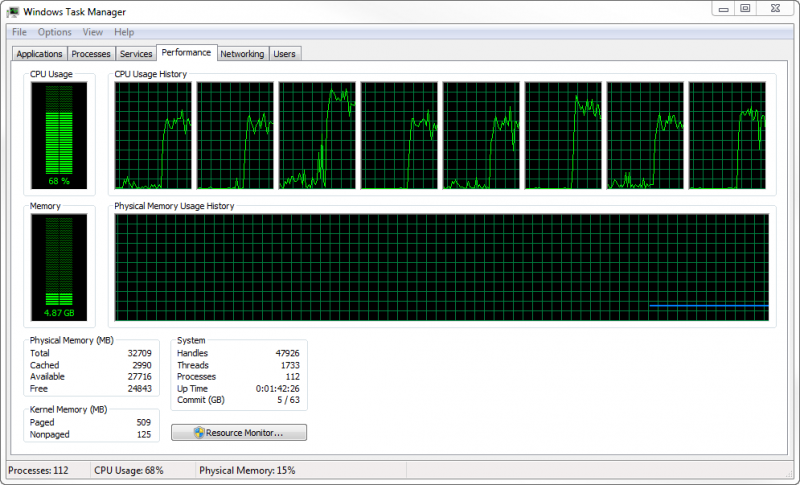
Dramatically improves performance on multi-core processors without the need to modify your data files. PFC splits the computational load during cycling among multiple threads on shared memory, multi-core architectures (i.e., laptops or PCs with multi-core processors). By default, PFC will use the optimal number of threads available on the host system. However, users can set the number of threads PFC uses during cycling.
All aspects of the computational cycle are multi-threaded:
- Time step calculation
- Equations of motion
- Force displacement law
- Contact detection

Domain
The domain is an axis-aligned bounding box. All model components (e.g., balls, walls, contacts, etc.) exist within the domain. The domain is fixed: it does not grow automatically as model components disperse. The domain boundaries can have four conditions:
- destroy;
- stop;
- reflect; and
- periodic.
As model components interact with the domain, one of these conditions is applied. The introduction of the domain greatly enhances PFC's ability to efficiently undertake spatial searching and contact detection, two important aspects contributing to the performance of simulations.
Efficient Spatial Searching and Contact Detection
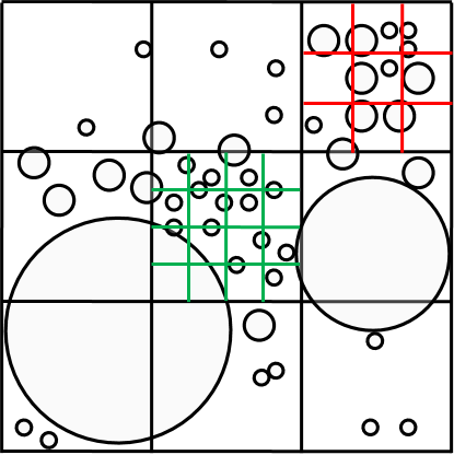
A cell-mapping scheme ensures that solution time increases only linearly with an increasing number of particles. Increase execution speed for complex particle-size distributions and rapid-flow problems by subdividing the domain into equally sized cells and dynamically refines or coarsens the cells to ensure optimal search performance in a multi-threaded environment. This approach provides near-optimal performance automatically.

64-bit version
Computers based on a 32-bit architecture can process 232 memory address locations of any information in virtual memory (RAM). Any memory not used by the computer's operating system is free for use by software applications like PFC and represents the maximum possible model size (approximately 2 to 3 GB, depending on the available hardware).
While this is sufficient for most PFC models, in cases where many hundreds of thousands of particles are required, model size begins to quickly outpace available memory. For example, in the figure below an SRM (synthetic rock mass) model 80 m on each side required over 800,000 particles for the required particle resolution. This model was too large to be modeled on a conventional desktop computer and required the newer 64-bit architecture. A 64-bit computer can process 264 addresses (16 billion GB) and is limited, for all practical purposes, only by the available hardware.
Thermal Model
The thermal model in PFC simulates the transient flux of heat in materials (conduction and storage in materials) and the subsequent development of thermally induced strains and forces.The thermal model may be run independently or coupled to the default mechanical model. Thermal strains are produced to account for heating of both particles and bonding material. Walls also may be assigned a temperature to act as a thermal boundary condition.
The thermal material is represented as a network of heat reservoirs (associated with each mechanical body) and thermal contacts (associated with each mechanical contact). Heat flow occurs via conduction in the active thermal contacts that connect the reservoirs. Radiative and convective heat transfer are not included in the present formulation. Thermally induced strains are produced in the PFC material by modifying the particle size. Mechanical contact models may also account for thermally induced forces. Once the thermal micro-properties are specified, subsequent loading or damage (in the form of bond breakages) will modify the number of active pipes, and thereby change the ability of the material to conduct heat. For example, as a bonded material is compressed and new active contacts form, the macroscopic thermal conductivity will be increased; but as bonds break and contacts become inactive, the macroscopic thermal conductivity will be reduced.
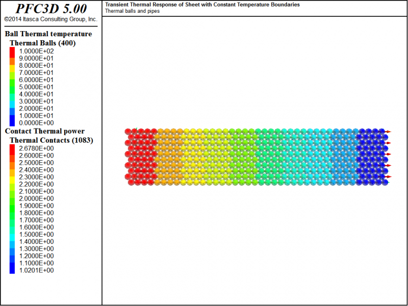
For example, a planar sheet of some width is initially at a uniform temperature of 0°C. The left side of the sheet is then exposed to a constant temperature of 100°C, while the right side is kept at 0°C. The sheet eventually reaches an equilibrium state at a constant heat flux and unchanging temperature distribution. Contour of ball temperature and thermal power vector field for a hexagonal packed system is shown below on the left. Modeled and analytical (Crank, 1975) normalized temperature distributions within the sheet, as a function of distance from the left side and time, are shown below on the right.

