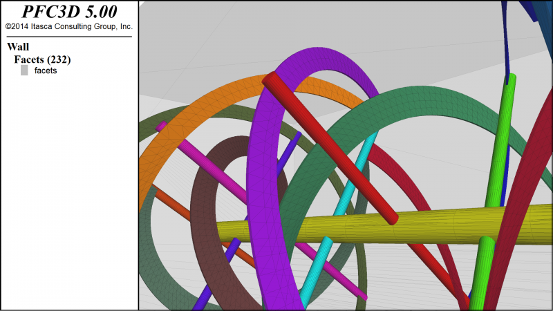
Faceted Wall and Geometry Data
Any number of arbitrarily-oriented line segments or planar convex polygons may be specified as walls, each with its own contact properties. Improved wall logic supports the importation of geometric surface data (3D triangular facets) from common file formats, including STL and DXF. The wall logic accurately and efficiently resolves contacts migrating across concave and convex edges. For example, a few simple commands rapidly imports and builds a complex set of walls ready to interact with balls and clumps.
Conveyor Walls
A rotational conveyor velocity can now be applied to wall facets for the general case of rotation of an axis symmetric wall (e.g., cylindrical drum) about its axis of symmetry. The wall does not rotate per se, but the facet conveyor velocities are set so that the wall's apparent behavior is rotation. In cases where the tangential velocity calculated at the centroid of a facet is not parallel to the facet face, the conveyor velocity is set to the projection of the tangential velocity onto the plane of the facet. Walls can also be rotated within the model domain about a specified center or rotation.
Contact Models
The Contact Logic is responsible for detecting and creating contacts in the course of the simulation. Contact models implement the contact constitutive law, depending on the process. For mechanical contacts, they relate relative motion of the contacting entities to the contact force and moment.
Null — The null contact model is the default contact model. No force or moment is generated.
Linear — The linear model reproduces the mechanical behavior of an infinitesimal, linear elastic and frictional interface that carries a point force. The interface does not resist relative rotation and optional viscous dashpots may be activated.
Linear Contact Bond Model — The linear contact bond model provides the behavior of an infinitesimal, linear elastic, and either frictional or bonded interface that carries a point force and does not resist relative rotation.
Linear Parallel Bond Model — The linear parallel bond model provides the force-displacement behavior of a finite-sized piece of cementitious material deposited between two pieces in the vicinity of the contact location, acting in parallel with a linear model.
LinearSoft-Bond Model — The soft-bond model can be used to simulate both unbonded and bonded systems. In an unbonded state, it provides the ability to transmit both a force and a moment at the contact point, with frictional strength parameters limiting the shear force, bending moment and twisting moment. NEW
Rolling Resistance Linear Model
— The rolling resistance linear model is based on the linear model, to
which a rolling-resistance mechanism is added. The effect of rolling
resistance at contacts between particles, and associated energy
dissipation, may be of major importance for many
granular applications in both dense, quasistatic and dynamic regimes.
Adhesive Rolling Resistance Linear Model
— A simple cohesive granular material is provided by the adhesive
rolling resistance linear model. The cohesion arises from a short-range
attraction, which is a linear approximation of the van der Waals force
law. The short-range attraction differs from the PFC bonded materials in
that there is no concept of breakage — i.e., the attraction is always
present whenever the interacting surfaces come within a specified
attraction range. NEW
Flatjoint Contact Model — A flatjoint contact simulates the behavior of an interface between two notional surfaces, each of which
is connected rigidly to a ball or pebble. The notional surfaces are
called faces, which are lines (PFC2D) or disks (PFC3D).
Smoothjoint Contact Model — The smoothjoint model simulates the behavior of an interface regardless of the local particle contact
orientations along the interface. The behavior of a frictional or bonded
joint can be modeled by assigning smooth-joint models to all contacts
between particles that lie on opposite sides of the joint.
Hertz Contact Model —
The Hertz contact model in PFC consists in a non-linear formulation
based on an approximation of the theory of Mindlin and Deresiewicz.
Hysteretic Contact Model — The Hysteretic contact model in PFC consists in a combination of the elastic portion of the Hertz model as described in the Hertz Contact Model document, combined an alternate dashpot group consisting in a nonlinear visco-elastic element in the normal direction.
Burger’s Model — Burger’s model simulates creep mechanisms by using a Kelvin model and a Maxwell model connected in series
in both the normal and shear directions.
C++ Plug-in
The C++ Plug-in includes the ability to make C++ FISH intrinsics (to speed computation) and to extend the physics embodied in a PFC model with new contact (i.e., constitutive) models in C++.
C++ FISH Intrinsics
Enables users to execute their own C++ code during a PFC simulation. User-defined FISH intrinsics are written in C++ and compiled as DLL (dynamic link library) files to be loaded whenever needed in a PFC simulation. The Visual Studio 2010 C++ compiler is used to compile the DLL files. This component can be used to replace selected FISH functions and thereby speed up execution considerably, especially when operating upon large numbers of model entities during each cycle.
C++ Contact Models
Enables users to add new contact models in PFC. A contact model describes the force-displacement response at a contact. During each cycle, the PFC program calls each contact model (passing in relevant information about the two contacting entities) and the contact model updates the force and moment acting in an equal and opposite sense on the two contacting entities. User-defined contact models are written in C++ and compiled as DLL (dynamic link library) files to be loaded whenever needed in a PFC simulation. The Visual Studio 2010 C++ compiler is used to compile the DLL files. Source files for all PFC contact models are provided to users. This component provides the flexibility to incorporate the physics relevant to particular problems into the distinct-element framework.
Contact Model Assignment
A new Contact Model Assignment Table (CMAT) brings flexibility, using the range logic, to assigning contact models without complex FISH functions. Upon contact creation, the CMAT provides the contact model and its properties (which may be derived from the properties of two contacting surfaces). As a result, complex models involving heterogeneous material properties can be synthesized in a straightforward manner.
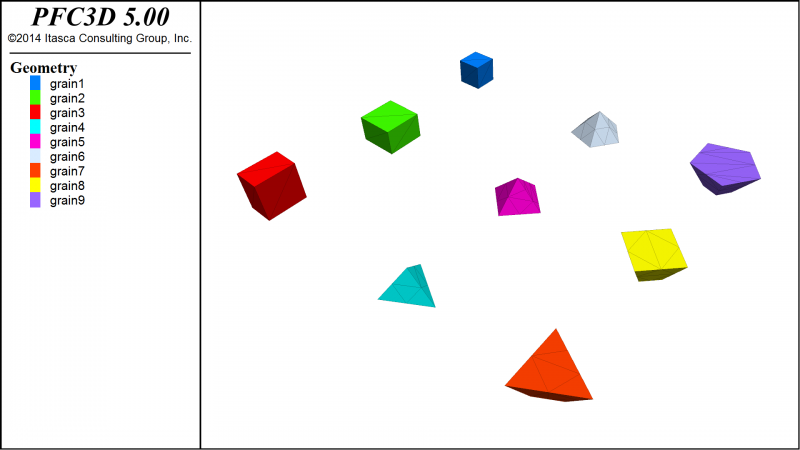
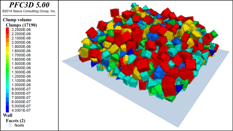
Clump Templates
Improved clump logic simplifies modeling of complex-shaped bodies. A clump is a set of rigidly attached spheres to which the user can assign inertial properties, their inertia properties can be calculated or specified, and they may be exported for reuse. Clumps are easily generated from templates, and can be visualized as particles or their surface description.
For example, the following STL surfaces can be imported into PFC and used as clump templates. Clump templates can be automatically generated from surface descriptions using a built-in Bubble Pack algorithm.
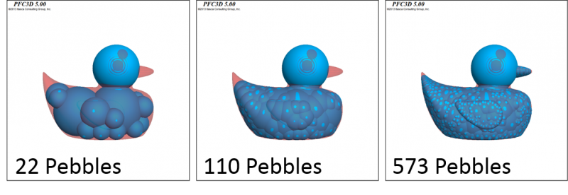
Bubble Pack
Automatically creates clump template particles for a specified triangulated surface using Delaunay triangulation and circumscribed circles (PFC2D) or spheres (PFC3D). The template parameters may be adjusted to balance the number of particles in each clump and the smoothness of the surface representation.
For example, the following rubber DXF file of a duck can be used to create a range of clump template depending on the desired surface accuracy and number of particles that are acceptable.
Bricks
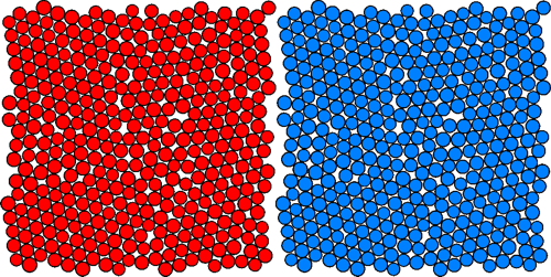
A brick is a compacted, bonded particle assembly that may be replicated many times to construct a large model. The brick is derived (in a separate PFC model) by compacting an assembly of particles within periodic space, and then storing it in compact form; copies of this assembly can then be fitted together perfectly, because the geometrical arrangement of particles on one side of a brick is the negative image of that on the opposite side (see image below).
There are two main reasons for constructing a model of attached bricks. First, a large model may be constructed very quickly because the bricks are already compacted and in equilibrium. (Note that contact forces are also stored within the brick, and these automatically balance at the junction between two bricks if the original forces were in equilibrium.) Typically, the time necessary to bring a model to equilibrium increases greatly with the size of the model, because information (about unbalanced forces) must be transmitted repeatedly across the entire model. When a model is constructed of already equilibrated bricks, no further time is necessary to establish global equilibrium. Thus, a large equilibrated model may be assembled almost instantaneously.
The second main reason to construct a model of bricks is that each brick may be replaced by a linear matrix form, in order to increase the speed of calculation. Linear versions of bricks are usually acceptable near model boundaries, where nonlinear mechanisms (such as cracks) are absent. There are two matrix forms:
- a stiffness matrix (denoted as a “full-matrix” brick) that is a one-for-one replacement of the translational degrees-of-freedom of the bonded-particle pbrick assembly; and
- a stiffness matrix (denoted as a “degenerate-matrix” brick) that corresponds to a single finite difference zone (or finite element) that replaces the brick.
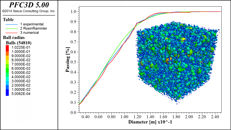
Size Distributions
Result in the targeted creation of complex assemblies of balls and clumps with overlaps until a target porosity is reached. Ball positions and radii can be drawn from uniform or Gaussian distributions throughout the model domain. A number of ball distributions, with radius ranges and volume fractions, can be specified. Given a size distribution, one can generate an assembly that satisfies it.