Slope Stability Analysis for T.H. 53 Relocation
This rock discontinuity characterization and slope stability assessment was part of the Highway 53 (T.H. 53) relocation project (completed September 2017). After collecting rock discontinuity information in an extensive field campaign, UDEC and 3DEC models were utilized to confirm that the mechanism of failure along the slopes is flexural toppling and the factor of safety is acceptable.
Project Background
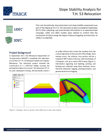
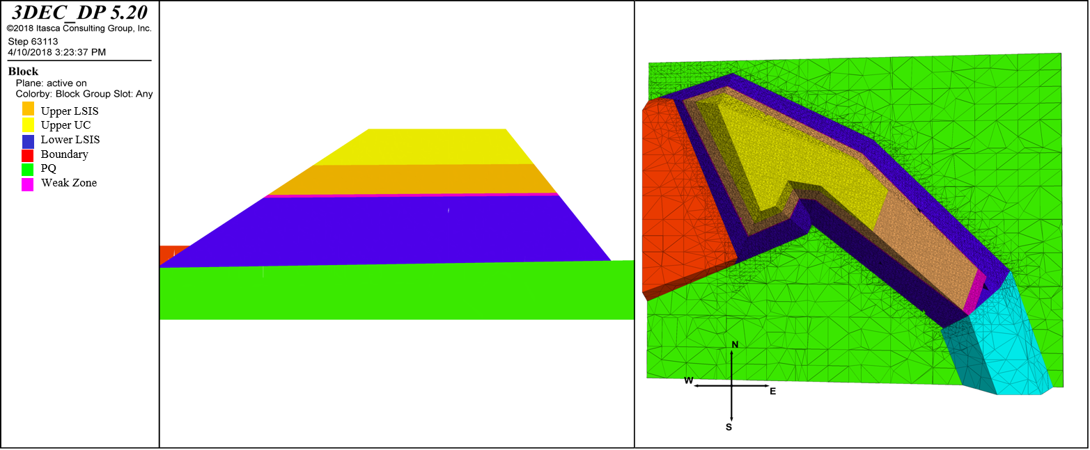
In September 2017, the Minnesota Department of Transportation (MnDOT) completed the relocation of a portion of T.H. 53 between Eveleth and Virginia, Minnesota. The relocation project included the construction of a 1,100-foot bridge crossing the existing Rouchleau iron ore pit. The relocation of T.H. 53, plus subsequent mining, will eventually create a so-called isthmus that carries the roadway from the current alignment to the east end of the bridge. Once mining occurs, the isthmus cross-section will be a trapezoid 300 ft wide at the top, with downslopes of 53 degrees, and up to about 500 ft deep (Figure 1). Information regarding rock bedding, jointing, and faulting was collected using three methods: down-the-hole televiewer logging; photogrammetry; and geomechanical core logging.
Model Description
The presence and orientation of subvertical joints indicated the possibility of flexural toppling along the isthmus slope. UDEC and 3DEC modeling was performed to confirm the existence of this mechanism and to assess the factor of safety.
UDEC Model Results
Following a kinematic analysis, which produced an acceptable safety factor for sliding and wedge failures, UDEC was used to model multiple sections of the isthmus to gain further insight into the flexural toppling failure mechanism. Six cross-sections along the isthmus were chosen, and properties of the bedding planes and joints were determined from geotechnical core logging, down-the-hole logging, and photogrammetry data. UDEC models were run both deterministically and stochastically. The factor of safety for each deterministic model was calculated using the strength reduction method (SRM), a function that is built into UDEC. The SRM involved reducing strength properties until failure to obtain a factor of safety for the slope.
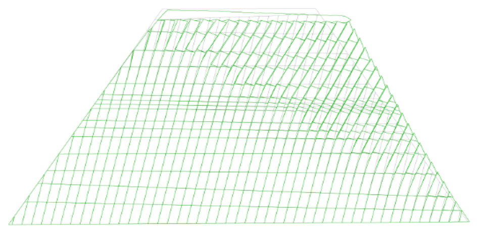
Figure 2 shows an exaggerated deformed shape of the slope. This view shows how the deep-seated flexural toppling mechanism is developing in the upper-right section of the slope.
3DEC Model Results
Initial UDEC models showed an unacceptable factor of safety, which motivated the creation of a three-dimensional model. In UDEC, a single 2D section cannot be cut perpendicular to strike on all joint sets, which means a 2D model is capturing apparent dip rather than true dip. Thus, a two-dimensional analysis cannot fully capture the three-dimensional interaction of the joints and the isthmus.
Joints created in the 3DEC model were based on the vertical-to-subvertical joint sets and subhorizontal bedding planes collected on site. In UDEC, all joints were discretely modeled, whereas in 3DEC, the subhorizontal bedding planes were not discretely modeled (to increase runtime). Bedding planes in 3DEC were modeled using the ubiquitous joint constitutive model.
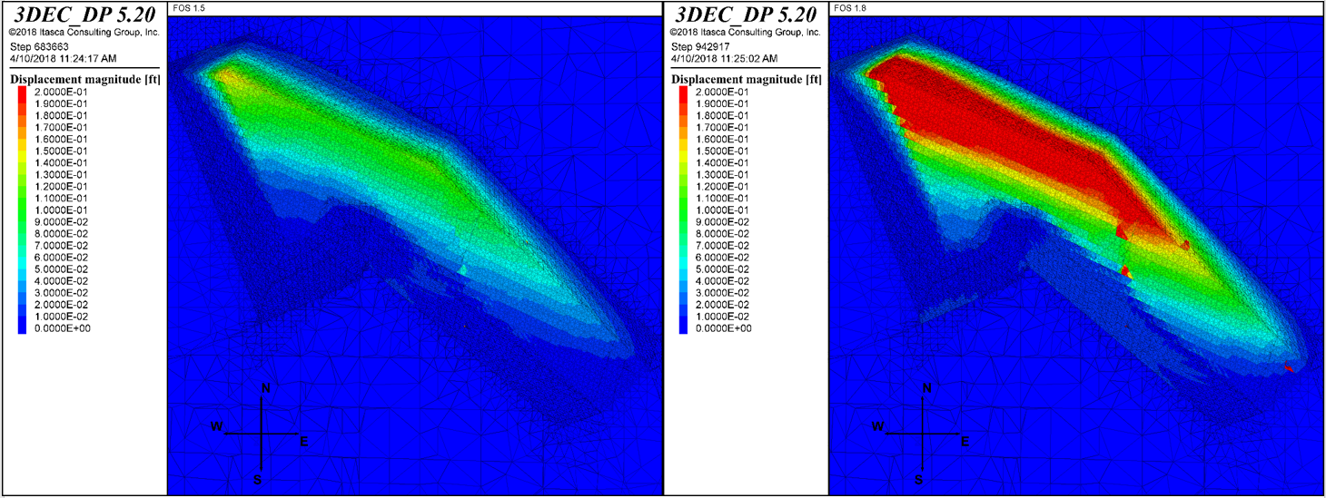
The final 3DEC model was stable up to a strength reduction factor of 1.5 but was unstable when the strength reduction factor was increased to 1.8. The left image in Figure 3 shows the surface displacements across the isthmus for a factor of safety of 1.5, where the maximum displacement is approximately 0.16 ft. When the strength reduction factor was increased to 1.8, the displacements continued to increase across the slope, so the slope was determined to be unstable. The right image in the same figure shows the displacements extending across the isthmus with a factor of safety of 1.8.
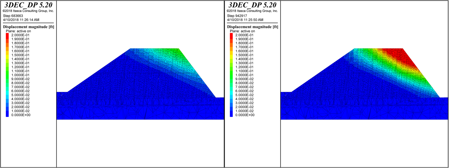
To further illustrate the failure mechanism, cross-sections were made at multiple locations along the isthmus to determine stability and the mechanism of failure. Figure 4 compares the displacements through a cross-section for strength reduction factors of 1.5 and 1.8, where it is possible to see the deep-seated movement in the slope associated with flexural toppling.
Summary
- It is necessary to use an appropriate numerical modeling software in order to address flexural toppling.
- A three-dimensional 3DEC model was created to capture the interaction of the joints with the isthmus slopes.
- The UDEC and 3DEC models both confirmed that flexural toppling is a mechanism of failure for the isthmus slope.
- The 3DEC model showed that the factor of safety of the slope is at least 1.5, which met MnDOT’s minimum requirements.
References
Brose, A. et al. (2018). "Slope Stability Analysis for TH53 Relocation, Virginia, MN," in Proceedings of the 69th Highway Geology Symposium, September, 2018, pp. 114-132.